
Workshop detail header
Workshop notes

Mechanical Bitcoin movement

Build logs, machining experiments, watchmaking notes, and lessons from trying to make a mechanical watch shaped by Bitcoin.

This is the main record of the project: what worked, what failed, what changed, and what I learned along the way.

2025/09/03 00:29 UTC
TLDRSurprisingly, a budget-friendly micro drill has outperformed its more expensive counterparts, effectively drilling 0.3 mm holes, which is impressive in the world of watchmaking. While larger, pricier machines often fell short, this simple tool delivered precision and reliability, proving that even "entry-level" equipment can hold its own in a professional setting. It's a reminder that sometimes the most unexpected tools can make a big impact, keeping the journey of watchmaking both challenging and rewarding. 🔧
Show more Show less
sketch

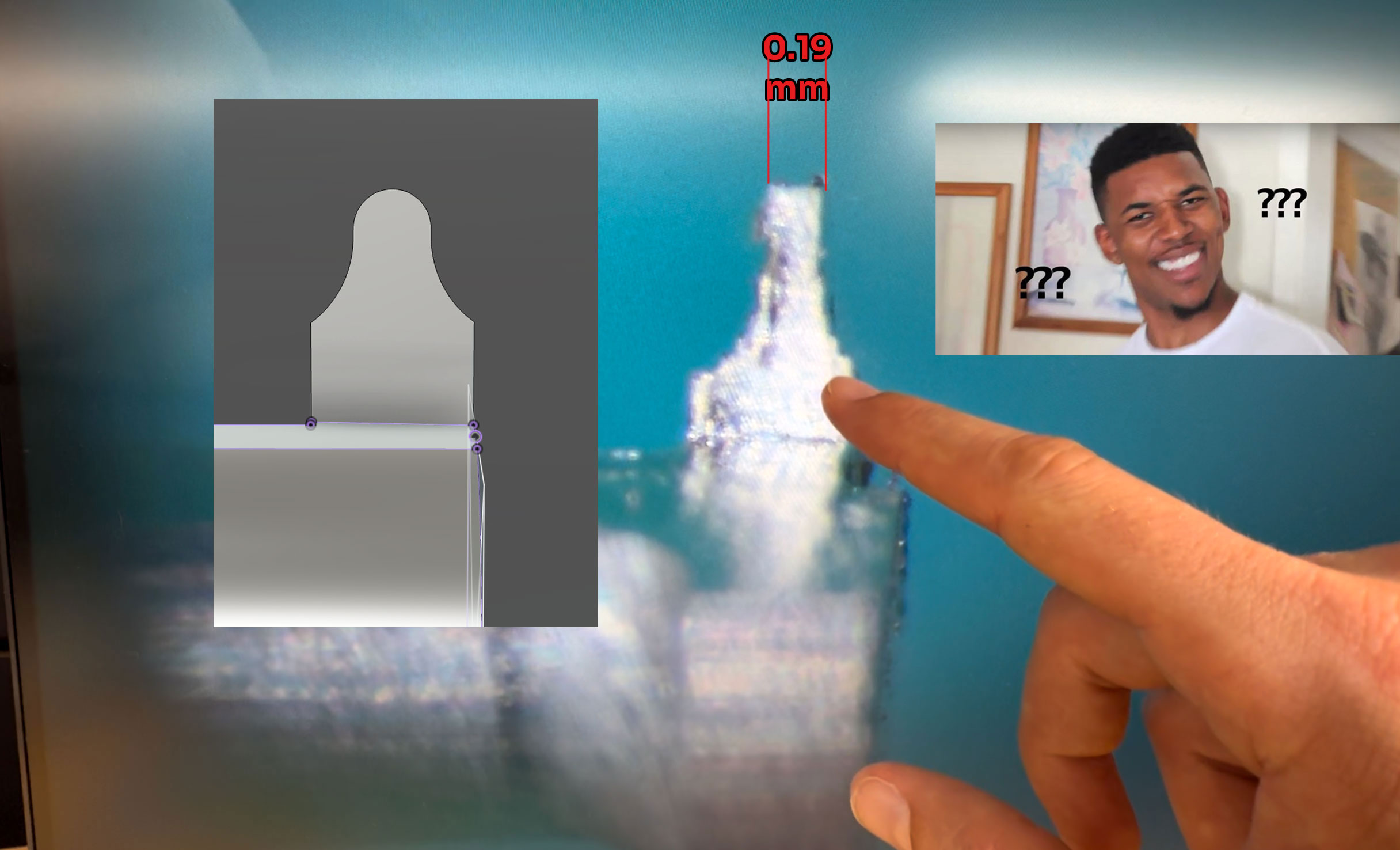
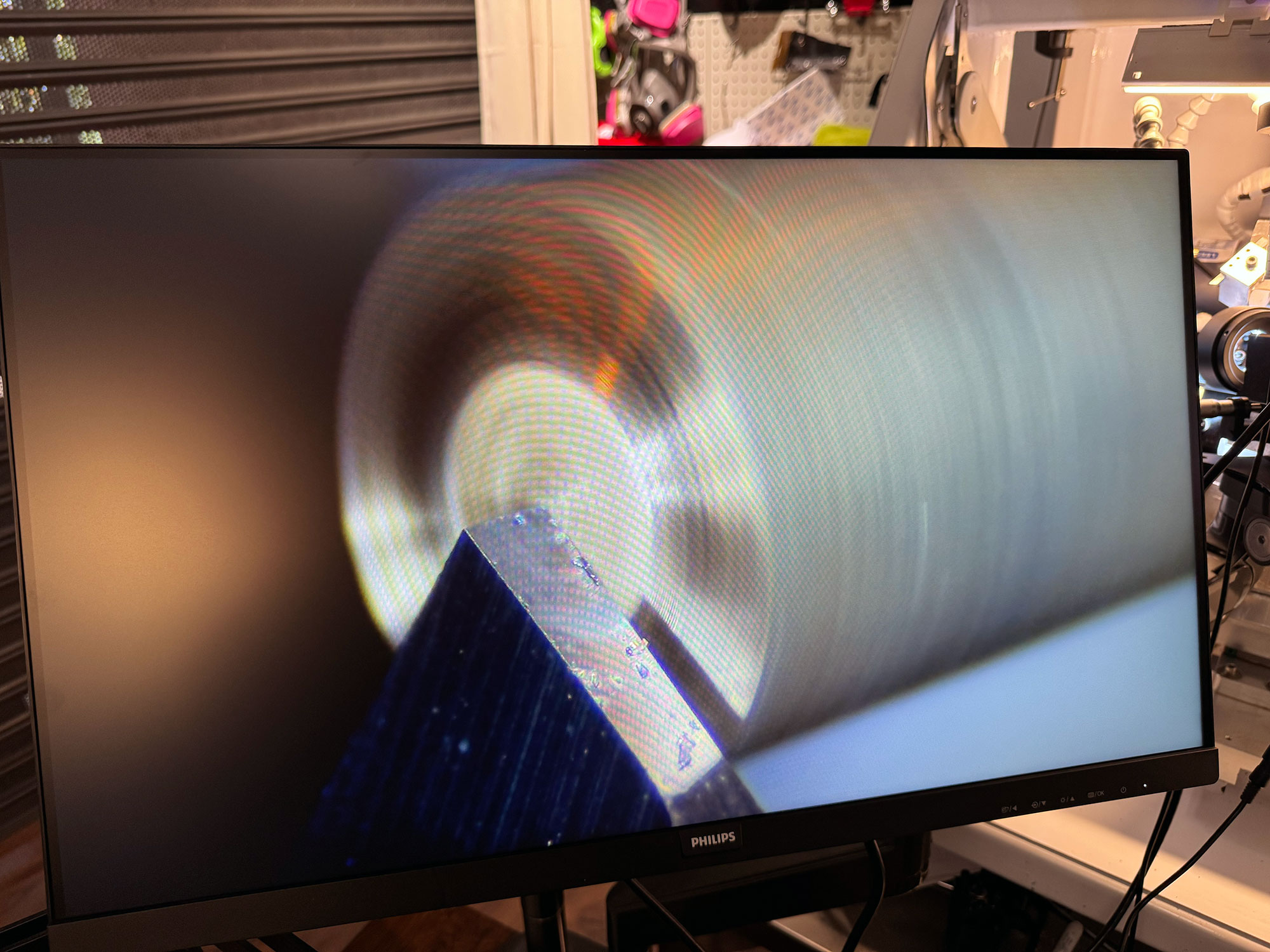
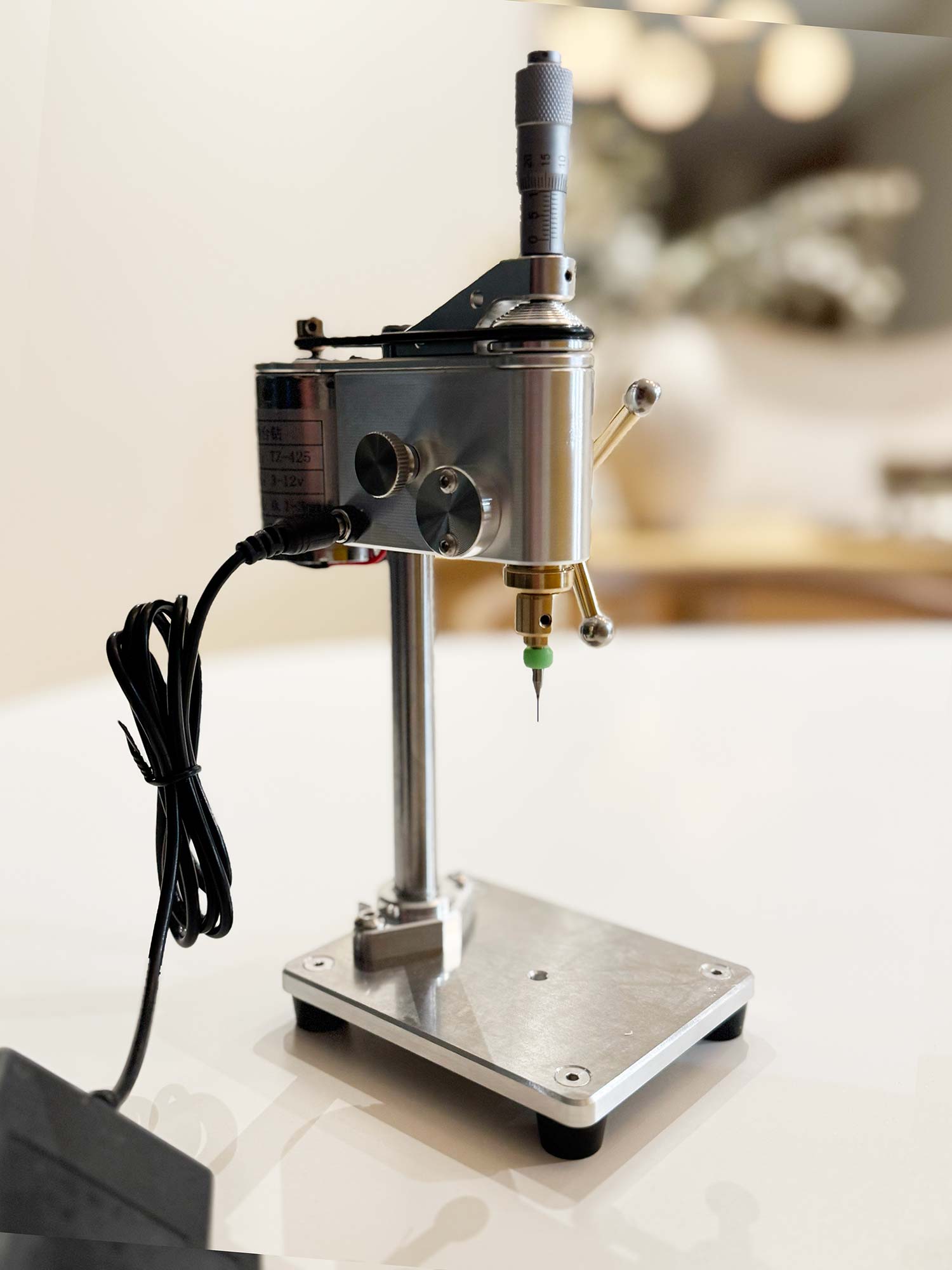
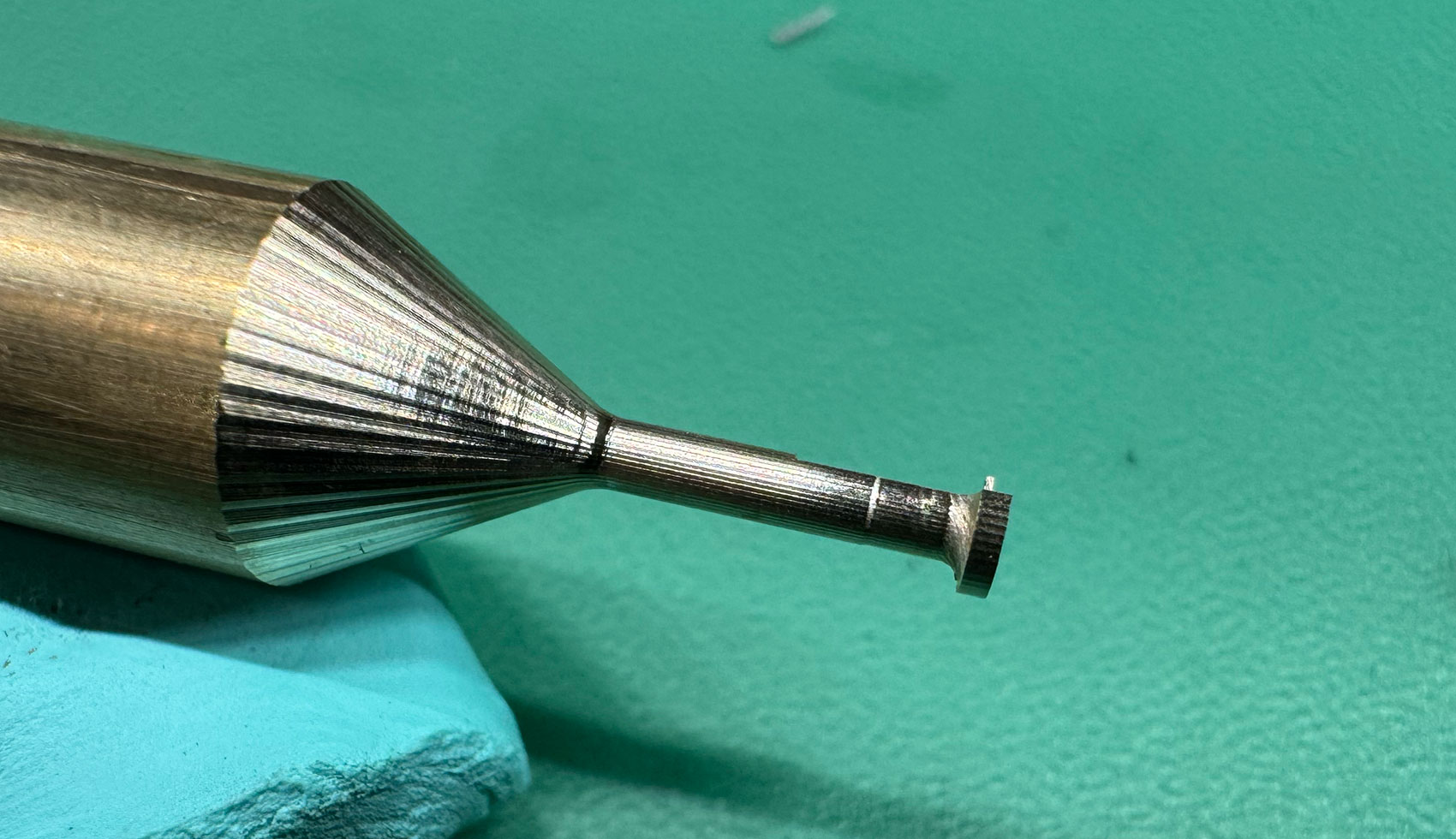
Today I set up a new tool on the bench: a micro drill. It was inexpensive, I didn’t expect much from it, and honestly, I assumed it would be more of a curiosity than a serious addition. To my surprise, it performed better than expected — drilling clean holes as small as 0.3 mm in diameter. For anyone who has worked in watchmaking, that’s quite impressive for such a modest machine.

Comparisons and Expectations

When I purchased my Elara 2 and Lathe 3, I was advised that my existing equipment — a Sherline mill and a traditional watchmaker’s lathe — were toys, and would not provide the level of precision required for professional results. That seemed fair at the time; after all, these tools are often categorized as entry-level or hobby-grade.

Yet, a year later, the contrast has been eye-opening. While the larger machines have severle underferformed, this small micro drill has quietly demonstrated the ability to handle delicate work with confidence. It wasn’t supposed to be a precision hero, but in this case it has shown what’s possible on a smaller scale.

The Value of Simple Tools

There’s something encouraging about this. The micro drill isn’t overcomplicated, it isn’t marketed as cutting-edge, and it certainly didn’t cost a fortune. But it delivered where I needed it to. Sometimes, the simplest tools can step up in ways that more complex systems do not.

Looking Ahead

I won’t claim this micro drill replaces a full CNC, or that it solves all the challenges of watchmaking. But it has reminded me that progress can come from unexpected places. Tools often described as “entry-level” or “for hobbyists” still have their place in a serious workshop. And in this case, they’ve proven surprisingly capable — drilling holes that the more advanced machines have not yet been able to produce in my experience.

It’s a small victory, but one that keeps me motivated. Watchmaking is a long journey, and sometimes the most pleasant discoveries come from the tools you least expect.
Read standalone post

2025/09/02 10:32 UTC
TLDRA year with the Elara 2 CNC machine taught me a ton about machining, but didn't deliver a single usable part due to its lack of promised precision. Despite trying everything, including professional help, the machine's performance fell short of the micron-level accuracy crucial for watchmaking. While the experience was a lesson in persistence and technical learning, it left a significant gap between expectation and reality, driving me to explore new hardware solutions.
Show more Show less

It’s been a full year since the Elara 2 arrived in my workshop. In that time, I’ve poured countless hours into learning, testing, measuring, and refining. From CAM strategies in Fusion 360, to experimenting with feeds, speeds, and even multiple spring passes, this year has been an education in CNC machining unlike anything I could have imagined.

What I Learned

I didn’t step into this as an expert machinist. Quite the opposite. The Elara was supposed to be my bridge into precision watchmaking — a machine marketed with ±0.00001″ accuracy (0.0003 mm) and ±0.0002″ repeatability (0.005 mm). Numbers like that made it sound like a tool perfectly aligned with the microscopic tolerances of horology.

Over the year, I learned how much goes into producing reliable parts: tool deflection, thermal drift, motion control, encoders, and the subtle ways CAM paths can influence a cut. These lessons are valuable in their own right. But they’ve also been overshadowed by one stubborn truth.

Zero Parts Produced

Despite all the effort, I have not produced a single usable watch component on the Elara. Every test, every trial, has run into the same wall: the machine simply cannot hold the advertised precision.

  • Air passes: about 4 microns off
  • Cutting aluminum:
    • X-axis: ~33 µm off
    • Y-axis: ~50 µm off
    • Z-axis: ~85 µm off

For context: in watchmaking, a 50 µm error might as well be a canyon. Wheels don’t mesh, pinions don’t seat, plates don’t align. The promise of micron-level accuracy never showed up in practice.

The Gap Between Promise and Reality

It’s not that I haven’t tried. I’ve worked with outside engineers, tested with professional tools, and even reached out to NSCNC repeatedly. I’ve done everything a reasonable user could do. And yet, the reality remains: one year later, not a single part.

The most difficult part isn’t just the lost time. It’s the gap between expectation and reality. Buying a machine based on a specification that later gets revised downward isn’t just frustrating — it undermines trust.

Looking Ahead

While the Elara hasn’t delivered, the year hasn’t been wasted. I’ve learned more than I thought possible about machining, measurement, and persistence. And I’m already exploring new hardware paths, from upgrading motors and encoders, to rewriting the machine profiles from scratch. If anything, this experience has strengthened my resolve to keep going — because in watchmaking, persistence is the only way forward.

Still, the fact remains: after one year, the Elara has given me plenty of lessons, but zero parts. And that, more than anything, says what needs to be said about its precision.

Read standalone post

2025/09/02 09:28 UTC
TLDRThe Elara 2 CNC machine's software issues, like corrupted settings files and a fragile licensing system, have been a major headache, halting operations unexpectedly. 🛑 These problems highlight how essential stability and clear support are for machine owners, who shouldn't have to pay extra just to keep their tools running smoothly. To avoid these pitfalls, I'm now creating customized profiles and configurations, ensuring my focus remains on crafting precision parts, not troubleshooting software headaches.
Show more Show less

One thing I never expected when I bought the Elara 2 was that a simple text file and a fragile license system could bring the entire machine to a halt. But that’s exactly what happened — not once, but multiple times.

The Case of the Corrupted Parameters

The parameters.ini file in Mach4 controls key settings for the machine. For reasons I still don’t fully understand, it sometimes corrupts itself. When that happens, the machine’s profile breaks completely. No alarms, no easy way to reset — just a dead profile that refuses to load.

Each time this happened, I reached out to support to ask: how do I fix it? Instead of a straightforward procedure or documentation, I was told to send files back and forth, with little clarity on what was actually going wrong. It left me with the sense that the software side of this machine had never really been built to recover gracefully.

The License Lockout

On top of that, the Mach4 license itself proved incredibly fragile. Changing a Windows username, updating the OS, or even small environment changes were enough to invalidate it. The license isn’t held by me as the owner — it’s held by NSCNC. That meant every time it failed, I had to go back to them for a new code.

When I asked for a replacement license, I was told I’d need to pay again. It felt less like a solution and more like a roadblock: instead of focusing on making parts, I was negotiating just to keep the machine running.

Why This Matters

For anyone considering a precision machine, stability matters just as much as accuracy. A CNC should not stop working because of a corrupted text file or a minor Windows change. And when it does, the path to a fix should be clear, documented, and included in the original cost of ownership.

Moving Forward

These experiences are why I’ve started building clean, replicable profiles from scratch. By writing my own macros, UI, and configuration files, I can control how the machine behaves — and avoid situations where a single corrupted file or license check renders it unusable.

I share this not to argue, but to document. Because at the end of the day, a watchmaker’s focus should be on precision parts, not corrupted INI files and unexpected license fees.

Read standalone post

2025/07/25 17:24 UTC
TLDRIn a clever DIY victory, using a Velcro-mounted touch probe, I finely tuned the A-axis of my machine to within microns. Despite its makeshift setup, the process proved highly accurate and repeatable, offering smooth operation without hiccups. Next up is perfecting the Y-axis tilt for flawless cuts, moving one step closer to machining perfection. 🔧
Show more Show less

Super excited! I finally dialed the A-axis to microns by referencing my ultra-precise touch probe—yes, the one temporarily Velcro-mounted to the spindle. 😂 It might look sketchy, but the numbers don’t lie.

Workflow was simple:

  1. Pop the probe on its fluffy Velcro nest.
  2. Run M905 for a quick Z-zero and X/Y skew check.
  3. Jog the A-axis, sample two points, and let the macro spit out the exact offset.
  4. Tweak until the readout hits 0.000°. Pure satisfaction.

The best part? Zero chatter, no e-stop drama, and repeatability within a few microns—even with the DIY mount. Next step: figuring out how to properly dial in the Y-axis tilt so every face is dead-flat. Onward to perfect cuts! 🔧⌚️

Read standalone post

2025/07/24 20:51 UTC
TLDRThe CAD for your probe fixture is done and off to the shop, with a month-long wait for machining. Meanwhile, your Macro M905 is refining its magic, now able to correct for minute setup errors, aiming for no deviation before the fixture returns. Fingers crossed for that perfect zero reading on every axis when everything's set up. 🔧
Show more Show less

The probe fixture finally made it from napkin sketch to finished CAD. I’ve queued the RFQ on mfg.com; the shop says about a month until brass chips fly on their end. Waiting is hard, but knowing the part will come back dead-square is worth it.

Macro M905 Still Steals the Show

While the fixture is off getting machined, the Lua macro keeps proving its value. In addition to auto-zeroing Z, it now lets me sweep the probe across the ceramic puck, sample two points, and calculate the tiny X/Y angle error of my current setup. Goal: drive that number to 0.000 ° before the new fixture lands.

Next Steps

  • Wait for the part: ~4-week lead time from the shop.
  • Tune the macro: refine the X/Y angle routine so the offsets drop into the table automatically.
  • Full dress rehearsal: when the fixture arrives, clamp it, run M905, and watch the mill hit perfect zero with no hand-wheel drama.

If all goes to plan, the first probe touch in the new nest will read 0.000 on every axis. Fingers crossed—and spindles ready. 🔧⌚️

Fixture

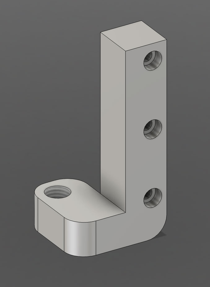
sketch

Read standalone post

2025/07/23 02:19 UTC
TLDRI just turned brass into precision gear teeth with a 0.4 mm carbide cutter, taking a wild ride from rough cuts to razor-sharp results in just a week. The process was a mix of trial, error, and some strategic skipping, but it ended with mirror-bright finishes and no mishaps. If you're into detailed machining, this one's worth a look! 🛠️
Show more Show less

First day turning pixels into golden curls! I sent a 0.4 mm carbide ball-nose through brass using a four-step plan (well, three plus a skip) and the chips did not disappoint.

What a week—literally. I built this entire setup in seven caffeine-soaked days, hit run, and hoped the cutter wouldn’t find a new way to redecorate my vise. Every spin of the spindle felt like a coin toss between triumph and catastrophic crash. Roller-coaster, meet workshop. 🎢

But the gamble paid off. I sent a 0.4 mm carbide ball-nose through brass using a four-step plan (well, three plus a skip) and the chips did not disappoint:

  • Pass 0 – Rough shape: big step-overs, big chips.
  • Pass 1 – Finer rough: tighter outline, heat still low.
  • Pass 2 – Relief angle: light plunge to free the flanks before final form.
  • Pass 3 – Skipped: brass ≠ tool—edge saved for the good stuff.
  • Pass 4 – Gear-tooth detail: feather cuts that leave razor-sharp teeth (rapid plunge mellowed just enough!).

The result? Mirror-bright flanks, zero burrs, and—most importantly—no emergency e-stop drama. Still buzzing from the adrenaline.

Love watch-scale machining? Smash that like, drop your questions, and subscribe so you don’t miss the A-axis run-out test.

gear tooth gear tooth

Read standalone post

2025/07/21 23:13 UTC
TLDRThe THREE.js CAM demo took its first flight, and it's as exciting as it sounds—think spinning cutters and twirling axes in a browser-based sandbox that's mimicking real machine paths. Watching the toolpath come to life with dynamic movement makes all those coding hours worthwhile. If you're curious, dive into the interactive playground to see this virtual machining magic for yourself. 🛠️✨
Show more Show less

Big moment—time to push pixels into motion and see if the browser-based CAM sandbox behaves like a real machine. Spoiler: the cutters danced, the A-axis twirled, and I grinned like a kid with a brand-new loupe. 😊

Watching the path morph in real time made all those late-night refactors worth it. The spindle spins, the passes layer up, and the code footprint shrinks with every arc conversion.

Curious? Load the sandbox, drop a few points, and watch the tools trace air:

Explore the interactive toolpath playground →

Read standalone post

2025/07/19 17:29 UTC
TLDRToday's G-Code update is a game-changer for smoother CNC operations: automatic pass-count adjusts cuts for different materials, arcs are now cleaner, and tool changes are seamless with new M6 support. The new code structure, with its tidy headers and footers, reduces machine downtime and stress, making programming more efficient and satisfying. If you're running a CNC, this update means less manual intervention and more precision—give it a spin and see for yourself! 🚄🔧
Show more Show less

Today the toolpath builder got a healthy dose of refinement—little tweaks that make the code cleaner, the machine happier, and me way less stressed. Here’s the highlight reel:

  • More passes, smarter chips. Added automatic pass-count logic so the engine tweaks depth and step-over based on cutter diameter. Brass, steel—each material now gets just enough nibbles to keep chatter away without wasting machine time.
  • Arc simplification. Goodbye clunky point-to-point lines! A quick geometry pass converts eligible segments into slick G2/G3 moves. Fewer commands, smoother motion, prettier cutter marks. The spindle feels like it’s gliding on rails. 🚄
  • Tool-change support. We finally speak fluent M6. Pick one cutter for rough, another for finish, and the post inserts a safe retract, spindle stop, and automatic offset call. No more pausing the CNC mid-cycle to swap tools by hand.
  • G-Code header & footer polish. Kicked off a tidy preamble—units, work offsets, RPM, coolant—so every file starts the same. The footer parks axes, shuts the flood, and drops a cheeky comment that logs cycle time. Consistency really is underrated bliss.
  • Visual reference on every angle. Each time the A-axis rotates, the viewer drops a translucent “ghost” of the cutter at the new orientation. It’s like leaving breadcrumbs in 3-D space—one glance tells you if the tool is clear of clamps before committing chips.

Watching the code scroll now feels oddly satisfying: fewer characters, cleaner arcs, and that crisp header/footer sandwiching everything into a neat package. Next on deck? I think I'll try it on the machine with an empty stock, but with a mill. 🔧⌚️

Explore the interactive toolpath playground →

Read standalone post

2025/07/17 22:24 UTC
TLDRDialing in a tool-centering camera is a precision task, almost like a watchmaker's job, but the effort pays off. With a dual-screen setup, neat wiring, and the perfect camera angle, getting those ultra-close shots has become more efficient and civilized. The challenge now is refining the Y-axis tool-centering routine for consistent accuracy, and once the A-axis rotation is perfected, it's full steam ahead with carbide bits. 🚀
Show more Show less

Took a breather from grinding CVD-tipped carbide bits and gave my eyes (and ears) a treat—camera alignment day! Getting the lens perfectly in line with a tool that’s barely thicker than a hair turned out to be its own little horological adventure.

Today’s mini-wins:

  • Dual-screen holder rig. Whipped up a two-arm stand so the inspection cam and its monitor hover as one unit. No more craning my neck between desk and machine—just glance, tweak, cut.
  • All wired, zero spaghetti. USB, power, HDMI—routed and zip-tied so nothing snags a moving axis. The garage looks… well, almost civilized. 😌
  • Found the sweet angle. A few degrees off-vertical gives just enough depth to judge tool height without hiding the cutting edge in glare. The moment the flute catches the light, you know you’re on plane.

Because the shot is crazy close-up, even stepping in front of the lens nudges the frame. The tripod quivers, focus wobbles—but it’s promising. A chunkier base or maybe a bit of mass-loading clay should calm those micro-tremors.

sketch sketch

Most machinists center a tool by reading the tip’s X/Y, subtracting half the diameter, and calling it good. Easy math—unless your headstock boasts a full Y-axis (tool height) like mine. That third coordinate means the classic “diameter ÷ 2” trick only gets me halfway. I’m experimenting with a quick probe routine: kiss the tool off a ceramic block, capture the video zero, then jog Y until the flute vanishes beneath a reference line on-screen. Still rough, but at least it’ll be repeatable.

Next up: heading back to those carbide-bit toolpaths—the last puzzle piece is rotating the A axis after every pass so the cutter always meets fresh stock. Lock that in and the chips can finally fly. 🔄🛠️

Read standalone post

2025/07/15 13:10 UTC
TLDRThis blog dives into a slick browser-based toolpath generator using THREE.js and React, transforming sketch or point-cloud inputs into animated, precise cutter paths without the hassle of G-code. Key highlights include spindle animations that visually indicate RPM and load issues, a parametric feed rate that color-codes speed, and easy geometry integration with JSON snippets. The real game-changer? It's all about geometry-driven intent rather than raw code, making it both user-friendly and safer for precision tasks. Perfect for those looking to streamline and visualize their CNC processes! 🛠️
Show more Show less

Another sprint in the virtual workshop and the browser-based toolpath generator keeps getting sharper. What started as a proof-of-concept—rendering cutter sweeps in THREE.js—now feels like a pocket-CAM you can open in a tab. The latest drop trades raw G-code import for something a little smarter: you sketch or paste a cloud of points, choose an offset distance, and the engine morphs that outline into a tight, back-and-forth tool dance complete with automatic retracts. No post-processor, no syntax errors—just pure geometry turned into motion.

Milling-bit animations. The spindle finally spins on screen! Each virtual tool carries its own loop keyed to your feed-slider, so a 12 000 RPM rougher whirls visibly faster than a 2 000 RPM finisher. It’s more than eye-candy: the motion helps spot mismatched step-overs at a glance—if the cutter’s screaming yet progress crawls, you know the chip load is off.

Parametric feed rate. Instead of parsing an F-word from G-code, a single slider now drives the linear feed for every segment the engine creates. During playback the toolpath hue shifts from cool blues at gentle feeds to warm ambers when you start pushing the limits. One glance tells you if your brass rough pass is baby-slow or your carbide micro-bit is about to cry.

Plug-and-play geometry. A refactor of the component library means adding new cutter shapes or diameters is basically a one-liner. Drop a JSON snippet—{ "type": "ballEnd", "diameter": 0.12 }—and the scene pulls in a pre-scaled STL, mounts it in the spindle, and wraps collision boundaries around the business end. Ideal when you’re juggling watch-scale tooling: need a 0.07 mm carbide ball nose? Pop it in, hit save, done.

Scroll-through collision hunt. The timeline now sports a buttery scrollbar that lets you scrub every move frame-by-frame. Potential crashes flash crimson, the camera snaps to the offending vertex, and the point-cloud offset updates live so you can widen clearances without playing detective. On a 4-axis barrel-arbor job—thousands of tiny A-rotations—that feature already saved me hours of forehead-denting.

Shape morphing instead of G-code. Here’s the big architectural twist. Rather than feeding the simulator raw NC code, you define intent: points that describe the part’s silhouette or an engraving loop. The engine expands that outline by your chosen distance, zigzags across the interior with an automatic step-over, and inserts retract hops at the boundaries. It then feeds those moves straight into the animation layer. Less control for now, but zero chance of a missing G00 sending the spindle through the table. Baby steps, but safe ones.

Tidy React hooks. Under the hood, React keeps state crisp while THREE.js handles shaders and meshes. I tossed out the imperative spaghetti, replaced it with functional hooks, and tidied context so the codebase finally feels as clean as the renders. Next stop: physics shaders so the chip-fling direction changes when the spindle tilts. Because why not? 🛠️

Explore the interactive toolpath playground →

Read standalone post

NOSTR:

npub1nvhq9vgkpahlugwcf3jsnpaq5lj3w3rk6lknnvf9r8h8ft2ja2asaqcn2a
Copyright 2025 The bitcoin watchmaker